与C丝带,第2部分:第一个功能区功能的应用程序
在这篇文章中,我们将继续我们的Windows功能区框架的功能在Windows 7给我们带来的审查。色带一般功能和特定的Windows功能区框架的更多信息,确保您阅读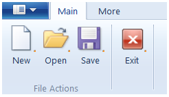 。
。
今天,我们将看到如何创建一个色带在C启用的应用程序使用Windows功能区框架。要显示它,我们将建立一个小型应用程序,用丝带将包含两个选项卡,三组,和几个按钮。
正如在以前的帖子中提到,有四个步骤,以创造一个带状的功能的应用程序,我们需要遵循。让我们深入这些步骤的细节。
最后要注意,在我们开始之前,这个职位需要在Win32和COM开发的知识。此外,如果你想编译连接到这篇文章的示例应用程序,请确保您有{A}安装。步骤1:定义功能区用户界面
要做的第一件事是申报功能区用户界面。这是通过创建一个XML文件,将使用基于XAML的语法包含功能区用户界面定义。
对于我们的演示应用程序,让我们创建文件名为RibbonMarkup.xml(xml后缀,是不是强制性的,但仍建议),具有下列内容:<?xml version='1.0' encoding='utf-8'?>
<Application xmlns='http://schemas.microsoft.com/windows/2009/Ribbon'>
<Application.Commands>
<Command Name="cmdButtonNew"
Symbol="ID_CMD_NEW"
LabelTitle="New"
LabelDescription="New Description"
TooltipTitle="New (Ctrl+N)"
TooltipDescription="Create a new image.">
<Command.LargeImages>
<Image>Res/New32.bmp</Image>
</Command.LargeImages>
</Command>
<Command Name="cmdButtonOpen"
Symbol="ID_CMD_OPEN"
LabelTitle="Open"
LabelDescription="Open Description"
TooltipTitle="Open (Ctrl+O)"
TooltipDescription="Open an existing image.">
<Command.LargeImages>
<Image>Res/Open32.bmp</Image>
</Command.LargeImages>
</Command>
<Command Name="cmdButtonSave"
Symbol="ID_CMD_SAVE"
LabelTitle="Save"
LabelDescription="Save Description"
TooltipTitle="Save (Ctrl+S)"
TooltipDescription="Save the current image.">
<Command.LargeImages>
<Image>Res/Save32.bmp</Image>
</Command.LargeImages>
</Command>
<Command Name="cmdButtonExit"
Symbol="ID_CMD_EXIT"
LabelTitle="Exit"
LabelDescription="Exit Description"
TooltipTitle="Exit (Ctrl+X)"
TooltipDescription="Exit application.">
<Command.LargeImages>
<Image>Res/Exit32.bmp</Image>
</Command.LargeImages>
</Command>
<Command Name="cmdButtonMoreA"
Symbol="ID_CMD_MORE_A"
LabelTitle="More A"
LabelDescription="Sub button A">
<Command.LargeImages>
<Image>Res/MoreA32.bmp</Image>
</Command.LargeImages>
</Command>
<Command Name="cmdButtonMoreB"
Symbol="ID_CMD_MORE_B"
LabelTitle="More B"
LabelDescription="Sub button B">
<Command.LargeImages>
<Image>Res/MoreB32.bmp</Image>
</Command.LargeImages>
</Command>
<Command Name="cmdButtonMoreC"
Symbol="ID_CMD_MORE_C"
LabelTitle="More C"
LabelDescription="Sub button C">
<Command.LargeImages>
<Image>Res/MoreC32.bmp</Image>
</Command.LargeImages>
</Command>
<Command Name="cmdTabMain"
Symbol="ID_CMD_TAB_MAIN"
LabelTitle="Main">
</Command>
<Command Name="cmdTabMore"
Symbol="ID_CMD_TAB_MORE"
LabelTitle="More">
</Command>
<Command Name="cmdGroupFileActions"
Symbol="ID_CMD_GROUP_FILE"
LabelTitle="File Actions">
</Command>
<Command Name="cmdGroupExit"
Symbol="ID_CMD_GROUP_EXIT"
LabelTitle="">
</Command>
<Command Name="cmdGroupMore"
Symbol="ID_CMD_MORE"
LabelTitle="">
</Command>
</Application.Commands>
<Application.Views>
<Ribbon>
<Ribbon.Tabs>
<Tab CommandName="cmdTabMain">
<Group CommandName="cmdGroupFileActions" SizeDefinition="ThreeButtons">
<Button CommandName="cmdButtonNew" />
<Button CommandName="cmdButtonOpen" />
<Button CommandName="cmdButtonSave" />
</Group>
<Group CommandName="cmdGroupExit" SizeDefinition="OneButton">
<Button CommandName="cmdButtonExit" />
</Group>
</Tab>
<Tab CommandName ="cmdTabMore">
<Group CommandName="cmdGroupMore" SizeDefinition="ThreeButtons">
<Button CommandName="cmdButtonMoreA" />
<Button CommandName="cmdButtonMoreB" />
<Button CommandName="cmdButtonMoreC" />
</Group>
</Tab>
</Ribbon.Tabs>
</Ribbon>
</Application.Views>
</Application>
确定,这可能看起来乍一看吓人,但它是比较容易理解。功能区用户界面定义文件有两个主要部分,命令和视图。
现在,我只想说,"命令"部分定义了不同的操作使用色带的UI控件,用户可以调用。每一个这样的命令是定义其所需的资源(字符串和图像)。后来,我们将编写的应用程序代码中的命令处理程序。
视图部分定义的UI控件,我们要使用和他们的带状布局。每个UI控件绑定到一个命令,从而将触发UI控件时执行(例如,按钮点击)。
的命令和视图部分的更多细节将检讨对未来的职位。
一个视图部分可以发现,在我们的演示应用程序的色带有两个标签,第一个选项卡有两个组的第二个选项卡包含一个组。每个组都包含一些按钮。换句话说:图1:第一个标签
