一个使用WPF的图形绘图工具
 简介
简介
这是一个关于WPF和绘图工具的文章。
代码结构是我在其他文章代码项目,类似的链接是:
背景
理解本文,您需要了解一些WPF技术。概念,如DrawingContext,FrameworkElement类及其用法,当然如何写XAML图形用户界面的东西。使用代码
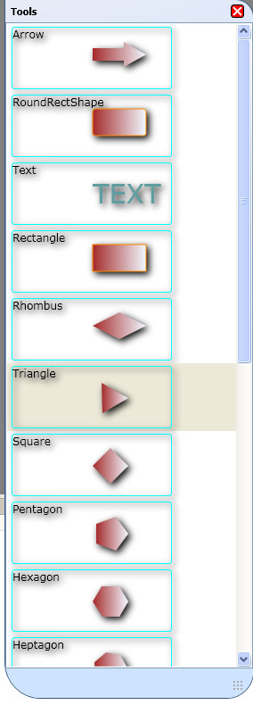
该项目首先创建一个工具框,就像下面:
{S0}
然后用户可以借鉴他们在屏幕上选定的形状,像下面:
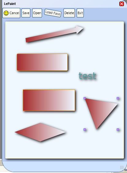
绘图,然后可以导出为XML文件或JPG文件。<?xml version="1.0" encoding="utf-8"?>
<ShapeList xmlns:xsi="<a href="http://www.w3.org/2001/XMLSchema-instance">http://www.w3.org/2001/XMLSchema-instance</a>" xmlns:xsd="<a href="http://www.w3.org/2001/XMLSchema">http://www.w3.org/2001/XMLSchema</a>">
<ShapeList>
<LeShape xsi:type="LeRectangle">
<ShowBorder>true</ShowBorder>
<LeBorderColor>
<A>255</A>
<R>0</R>
<G>0</G>
<B>0</B>
</LeBorderColor>
<BorderWidth>1</BorderWidth>
<Rect>
<X>300</X>
<Y>157</Y>
<Width>79</Width>
<Height>65</Height>
</Rect>
<LeFromColor>
<A>30</A>
<R>255</R>
<G>0</G>
<B>0</B>
</LeFromColor>
<LeToColor>
<A>30</A>
<R>255</R>
<G>255</G>
<B>255</B>
</LeToColor>
<LightAngle>225</LightAngle>
<Fill>true</Fill>
</LeShape>
<LeShape xsi:type="RoundRectShape">
<ShowBorder>true</ShowBorder>
<LeBorderColor>
<A>255</A>
<R>0</R>
<G>0</G>
<B>0</B>
</LeBorderColor>
<BorderWidth>1</BorderWidth>
<Rect>
<X>174</X>
<Y>230</Y>
<Width>84</Width>
<Height>74</Height>
</Rect>
<LeFromColor>
<A>255</A>
<R>0</R>
<G>0</G>
<B>0</B>
</LeFromColor>
<LeToColor>
<A>255</A>
<R>127</R>
<G>255</G>
<B>212</B>
</LeToColor>
<LightAngle>225</LightAngle>
<Fill>true</Fill>
<Radius>10</Radius>
</LeShape>
<LeShape xsi:type="ZoneShape">
<ShowBorder>true</ShowBorder>
<LeBorderColor>
<A>255</A>
<R>0</R>
<G>0</G>
<B>0</B>
</LeBorderColor>
<BorderWidth>1</BorderWidth>
<Rect>
<X>132</X>
<Y>97</Y>
<Width>90</Width>
<Height>84</Height>
</Rect>
<LeFromColor>
<A>30</A>
<R>255</R>
<G>0</G>
<B>0</B>
</LeFromColor>
<LeToColor>
<A>30</A>
<R>255</R>
<G>255</G>
<B>255</B>
</LeToColor>
<LightAngle>225</LightAngle>
<Fill>true</Fill>
<TextField>
<ShowBorder>true</ShowBorder>
<LeBorderColor>
<A>255</A>
<R>0</R>
<G>0</G>
<B>0</B>
</LeBorderColor>
<BorderWidth>1</BorderWidth>
<Rect>
<X>237</X>
<Y>112</Y>
<Width>58</Width>
<Height>22</Height>
</Rect>
<LeFromColor>
<A>30</A>
<R>255</R>
<G>0</G>
<B>0</B>
</LeFromColor>
<LeToColor>
<A>30</A>
<R>255</R>
<G>255</G>
<B>255</B>
</LeToColor>
<LightAngle>225</LightAngle>
<Fill>true</Fill>
<Caption>Shape 2</Caption>
<LeTextFont>
<Size>10</Size>
<Name>Tahoma</Name>
<Style>Regular</Style>
</LeTextFont>
<LeTextColor>
<A>255</A>
<R>255</R>
<G>0</G>
<B>0</B>
</LeTextColor>
<TextSize>10</TextSize>
</TextField>
<Caption>Shape 2</Caption>
</LeShape>
</ShapeList>
</ShapeList>
这个XML文件,然后可以重新打开这个项目后,最终用户可以编辑自己的图纸再次。
以下是这个项目的源代码的交代。
该项目首先创建画布上的GUI使用以下行:{C}
上面的代码首先创建一个阴影边框,边框内Grid控件,所以它会填充网格的细胞。然后什么的里面这条边界,它的一个帆布控制,这帆布里面的内容是只是一个框架元素,我们的DLL(CustomRender),它是一个元素,然后我们使用这个元素的DrawingContext,提请所有我们的形状手动。 DrawingContext是像WinForm中的图形对象。
我们customrender只是一个框架元素,它仅接受视觉对象。最重要的是,它执行两个功能:// Provide a required override for the VisualChildrenCount property.
protected override int VisualChildrenCount
{
get { return childrens.Count; }
}
// Provide a required override for the GetVisualChild method.
protected override Visual GetVisualChild(int index)
{
if (index < 0 || index >= childrens.Count)
{
throw new ArgumentOutOfRangeException();
}
return childrens[index];
}
然后在我们的代码,我们只需要添加可视对象的可视对象集合。netframework会使我们这个CustomRender对象。
我们使用反射来形成我们的控制器类,第一只创建一个形状,然后添加以上CustomRender类形状的视觉对象。 Point pt = e.GetPosition(myCanvas);
ConstructorInfo constructor = myTool.GetConstructor(new Type[] { typeof(Point) });
CurShape = constructor.Invoke(new object[] { pt }) as LeShape;
shapeCollection.AddObject(CurShape.myVisual);
当我们想得出这样的形状,我们可以随时调用下面的方法: DrawingContext dc = myVisual.RenderOpen();
Draw(dc);
if (selected)
{
if (bounds.Width > 5 && bounds.Height >5)
{
DrawPoints(dc, bounds);
}
}
dc.Close();
RenderOpen DrawingVisual方法将为我们打开一个DrawingContext,那么我们可以得出我们的对象,如果选择了形状,然后我得出几个跟踪点。所有这些之后,我们必须调用DrawingContext的Close方法,这告诉我们已经完成了这种视觉绘图。
这WPF的版本我的绘图工具的原则,如果你是intertested的,你可以得到这个绘图工具,以及对我的WinForms版本的更多信息。兴趣点
你学到什么有趣/有趣/恼人的同时编写代码?你做了什么特别聪明或野生或滑稽吗?历史
保持你在这里作出任何更改或改善的运行更新。